


 中文
中文 Italian
 Türkçe
 Português
 Español
 Deutsch
 العربية
 Tiếng Việt
 Français
 Русский


Ms.Lizzy
Hi, this is Lizzy from Dinosaw ( Not a Robot ). Which Machine ( model ) do you want? Please WhatsApp us now
Open Hours:8:30am-20:30pm
WhatsApp: +86 198-5901-3937
 Nov 15, 20255 MIN READ
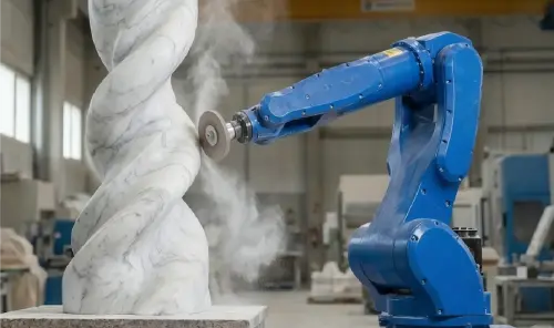 Nov 15, 20255 MIN READ
Go inside a robotic polishing system. Learn how the 6-axis robot arm, force control polishing systems, and software deliver a perfect finish on complex stone.
 What is a Robotic Polishing System, Really?
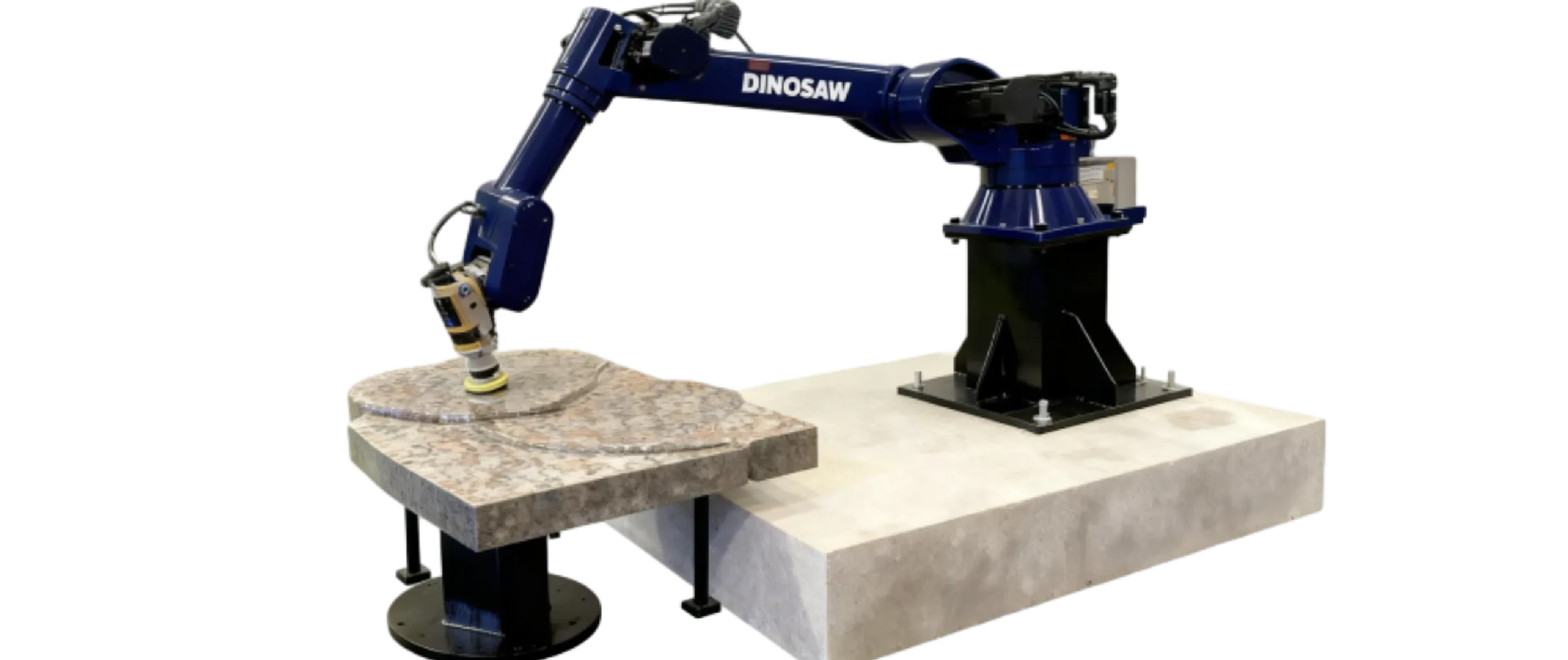
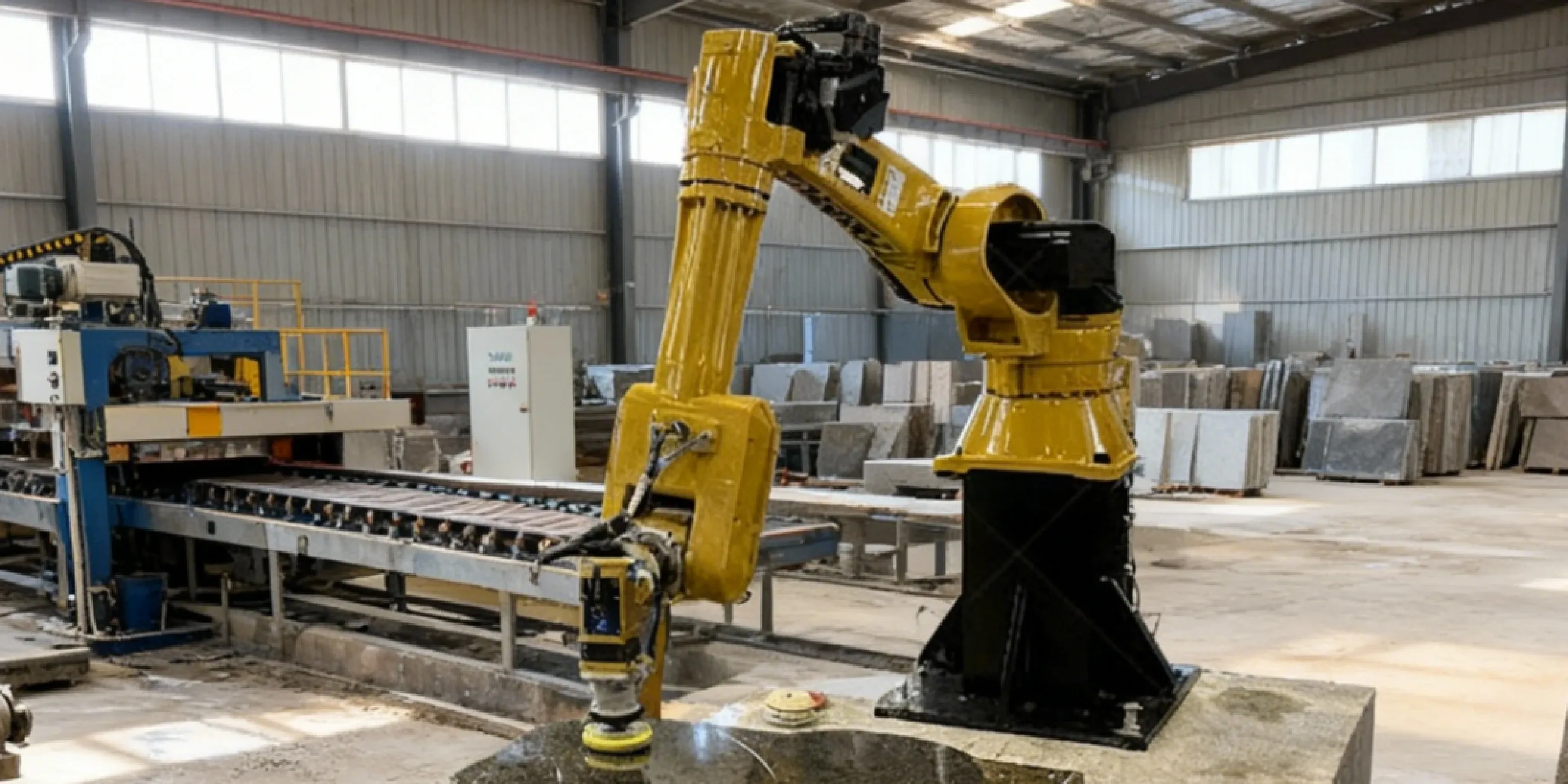
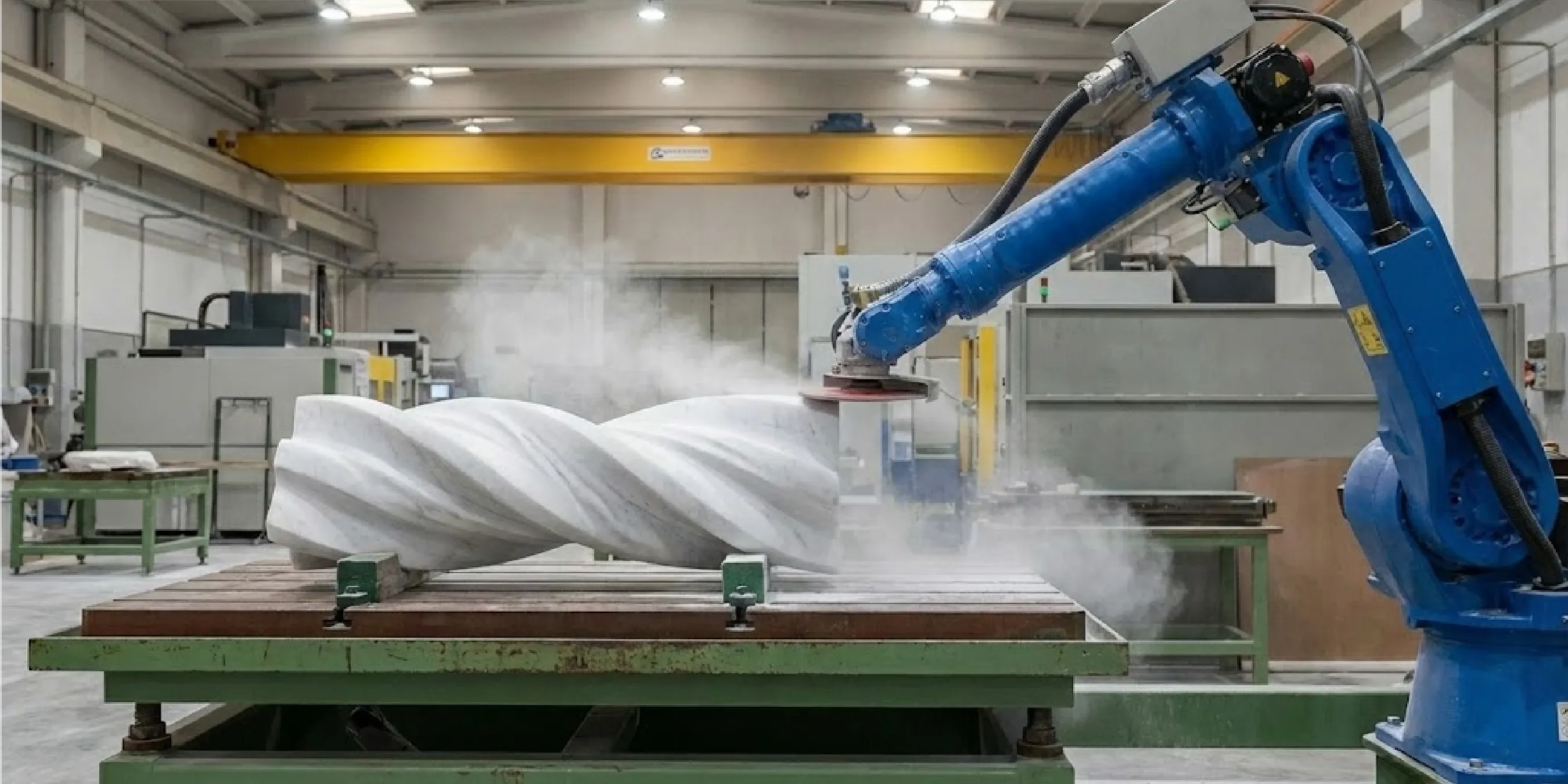 Anatomy of a Robotic Polishing System: Core Components
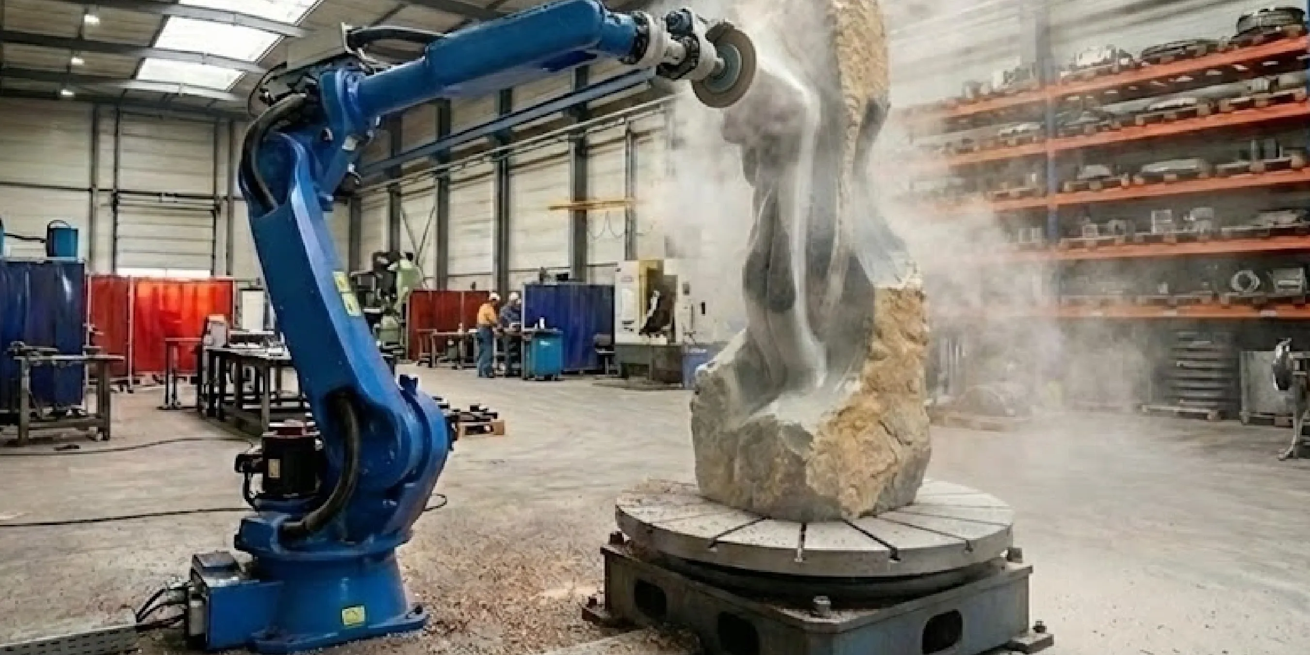 Robot vs. CNC Polishing: Which Performs Better?
The primary advantage is adaptive consistency. A human can't maintain the exact same pressure for eight hours. A CNC can't adapt to a slight surface variation. A robot can do both.
Factor | Robotic Polishing System | Traditional Methods (Manual/Simple CNC) |
|---|---|---|
Quality on 3D Surfaces | Exceptional. Force control ensures a perfect, uniform finish on curves, corners, and complex geometries. | Highly variable. Prone to swirl marks, uneven gloss, and operator fatigue. CNCs struggle with non-flat surfaces. |
Repeatability | Near-perfect. Every piece is polished identically, enabling true mass customization and reliable quality control. | Low. No two manually polished pieces are exactly the same. |
Labor Requirement | Reduces reliance on highly skilled (and scarce) artisans. One operator can often supervise multiple cells. | Requires highly skilled, experienced polishers who are physically engaged throughout the process. |
Data for QC | The system can log all process parameters (force, speed, cycle time) for every job, creating a digital quality record. | No data logging. Quality control is based on visual inspection only. |
 Frequently Asked Questions (FAQ)
 English
Get A Easy Solution
Chat Online
Hi, this is Lizzy from Dinosaw ( Not a Robot ). Which Machine ( model ) do you want? Please WhatsApp us now
Hello 👋 How can we help?